In this tutorial, we shall illustrate the use of the FOMCON toolbox in connection with the problem of designing a controller for a system with a significant input-output delay. For this purpose, a fractional-order first-order plus dead time (FO FOPDT) system is considered. We treat the continuous-time case.
1 Control design goal
Consider a system, that exhibits fractional-order dynamics, as well as a comparatively significant input-output delay, and is accurately described by a fractional-order transfer function
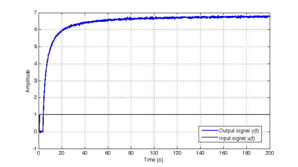
We assume, that the actuator of this system saturates at $u=\pm 1$. Suppose also that the "ideal" transfer function (1) is not known. However, experimental data from a step experiment is available:
In what follows, we use the tools available in the FOMCON toolbox to identify the system and design a suitable controller by means of constrained optimization.
2 System identification
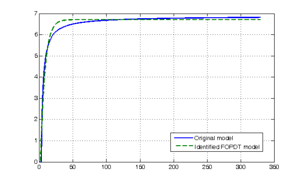
Our first task is to identify the system from the experimental dataset shown in Fig. 1. To identify the system, we may use the fractional-order transfer function time-domain identification tool (fotfid).
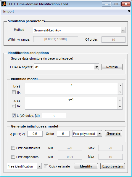
From observation of the registered transient response, we can conclude, that the system may be described by a first-order model with the static gain being close to $7$. Additionally, an input-output delay is observed and is close to $3$ seconds. Thus, our initial guess model is
and may be entered into the tool text fields as shown in Fig. 2. With this initial model, the system is identified in several iterations, and after a simple transformation1 using the normalize() command the system becomes
In the next section we shall use this model to obtain a fractional-order PID controller for the plant in (1).
3 Controller design
The first step in controller design is choosing a suitable controller structure. In this case, we are concerned with the design of a fractional-order PID controller. However, the plant to be controlled exhibits a significant input-output delay. Therefore, we consider using a Smith predictor [1]. The basic structure of the predictor is given in the next figure.
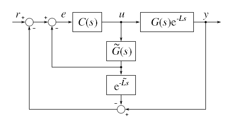
The design of the controller $C(s)$ is carried out in two steps. First we formulate an integer-order PID controller, and then optimize the parameters of the obtained controller, including the orders of the integrator and differentiator, finally arriving at a fractional-order PID controller working in a Smith predictor based control scheme. Note, that we use the parallel form of the PID controller.
3.1 Conventional PID controller tuning
We now describe the procedure for tuning a classical, integer-order PID controller for a fractional-order plant in FOMCON. We can use the iopid_tune graphical tool to first approximate the fractional-order model by a conventional FOPDT model, and then apply classical tuning formulae to get the PID controller parameters.
Suppose, that the identified plant has a workspace name of Gp. Then, we can use the integer-order PID tuning tool and fill the data field of the Fractional plant model box as shown in the following figure.
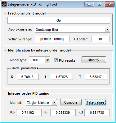
The fractional-order model is thence identified:
The result of the approximation is illustrated on the following figure.
Now we use the Ziegler-Nichols tuning formula to obtain PID controller parameters:
We shall use these parameters as the point of departure for our fractional PID controller design.
3.2 Fractional-order PID controller optimization
The design is carried out using the fpid_optim tool. Since a custom controller structure is used, we shall use Simulink for evaluating the characteristics of the transient response of our system. We set the parameters of the optimization as shown in Fig. 6.
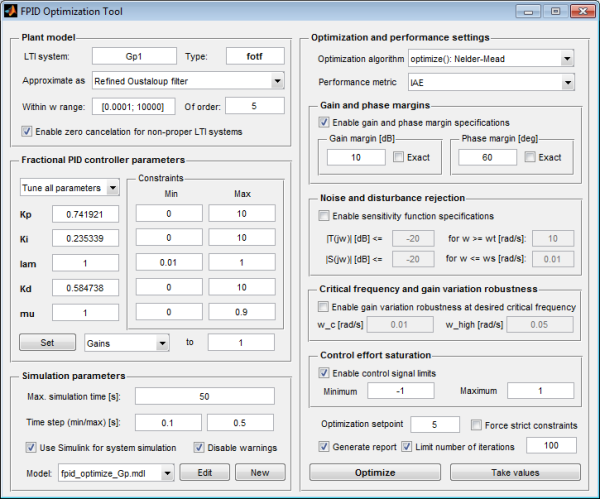
You may notice, that we use an LTI system Gp1 instead of the aforementioned Gp, which is exactly the same system with the delay term removed, since it is compensated for by the predictor.
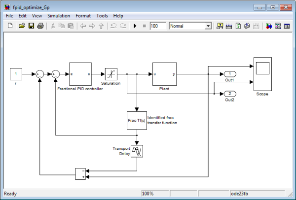
Now we need to build the Simulink model. We start by creating a new model fpid_optimize_Gp.mdl, which is a copy of the default model, and then clicking the Edit button. The model should open in a Simulink editor window as shown in the next figure.

Our task now is to modify this model and to add the predictor in Fig. 3. The identified model is added as part of the predictor, while the original, "ideal" model is added as the plant replacing the block in the inital model. With this setup it is also possible to evaluate the impact of the difference of the reference and original model on the control system. The resulting model is shown in Fig. 8.
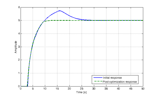
We can now proceed to optimize the controller. After 100 iterations, the following controller is obtained:
The results2 of the optimization are presented in Fig. 9. A clear improvement of the control system performance can be observed.
Conclusions
In this tutorial, we have illustrated the application of the FOMCON toolbox to the problem of designing a fractional-order controller for a process, exhibiting both fractional-order dynamics and a significant delay. The obtained results are considered satisfactory. However, in case of a real system the described procedure may need corrections, depending on particular performance specifications.
References
| [1] | N. Abe and K. Yamanaka, “Smith predictor control and internal model control – a tutorial,” in SICE 2003 Annual Conference, vol. 2, 2003, pp. 1383–1387. |

44 Comments
Hi ALEKSEI,
I am trying to repeat this exercise. Up to point 2, I don’t have any issue.
Could you please share figure 8 model with needed LTI model?
I want to learn FPID for Input/Output System.
Thanking You,
Hi Pritesh,
Sorry; the model supplied in the figure description was the one without the predictor implementation. I have corrected that now.
Hi ALEKSEI,
Thanks for your kind reply.
In model given by you, there is block called Fractional PID Controller.
Inside that block, it is FPID LTI. In that there is LTI function fpid_optimize_fpid.
How should I create the same? Is it Fractional Transfer function of FPID?
I have created ft type of Fractional Controller. Error: The “LTI system variable” parameter of the LTI block must be set to a valid LTI model
Please advice me…..
Once again Thanks
This model should be used with the FPID Optimization tool (Figure 6). You may set the model in the Simulation parameters options box. The model must be present in the current workspace. Otherwise, if you just want to simulate the transient response, you may replace the controller and the plant with those described in the tutorial using blocks from the FOMCON Simulink library.
Hi ALEKSEI,
I agree with your comment. FPID Optimization tool will give me fotf type of object. But in simulation, Fractional PID Controller block needs LTI Block.
How should I get LTI block from FPID Optimization tool ?
Once again thanks for your kind reply.
You may use the fractional PID contorller block from the FOMCON Simulink library.
sir,after several iteration for initial guess model we are doing the normalize for fractional order transfer function ,but here it is showing same initial model????????.can u help me please.,.,.,.,.
Please provide a screenshot depicting this situation.
sir,
wht is the function to open fomcon Simulink library…
Hi Aleksei,
In this tutorial why we use saturation block ? what is function of this block in this model ?
Thanking You
The block models actuator saturation. This is a purely physical phenomenon caused by limitations of what the actuator can actually produce (for example, a pump with max. displacement capacity of 100L/min cannot pump 200L/min).
sir,
Can this tool be used for an integer order plant transfer function..should the plant transfer function changed into an fractional order ..or else is there any way to change it from the toolbox.please suggest..
Thanking you
Yes, the tool supports conventional (i.e. integer-order systems) as well. You can also convert
tfobjects intofotfobjects, since the former is technically a subclass of the latter.sir,
can you just give me an example of using this toolkit with an integer order plant transfer function…I will be very thankful as I tried a lot…
thanking you
See, for example, page 126 of the “Fractional-order Systems and Controls: Fundamentals and Applications” book in https://fomcon.net/fo/overview-of-literature/
i dont have fopid matlab block.what can i do?
I do not understand what the problem is.
Sir,
how would i get the FOMCON simulink library? Is it present in MATLAB software or we have access it seperately? Please help me ?
It is included with the toolbox distribution which you can obtain from this website.
I download the FOMCON toolbox and follow the path as you suggest on your site to add toolbox in MATLAB, but i could not open the toolbox in MATLAB. what should i do?
Could you elaborate? What exactly does “could not open the toolbox in MATLAB” mean?
how to apply astrom hagguland method tofind kd value at particular phasemargin where as kp,ki fromknown zigler nicholas method and how to tune fractional order pid fromthese two methods because i am doing a project on tuning and analysis of fractional order pid please reply as early as possible
Hi sir,
I have downloaded this toolbox.This is an awesome toolbox.It gives wonderful control response of the plant.Thank you very much.
how to find lamda and mu
In this case they are obtained by means of optimization.
i am a student in ms degree i am so eager to share my science results and my researches and i want to know more about the pid-fractional order. please guide me with best regard. m.hedayati.kh@gmail.com
how to get fpid optimisation toolbox
please help me in this regard
I do not know what you mean by “fpid optimisation toolbox”. In FOMCON, you have the
fpid_optimtool. You may use that.Hello sir,
Refer above steps for first order process with delay system and optimize it using fopid_optim tool, but i found some error,
Error renaming “C:\Program
Files\MATLAB\R2013a\bin.42-beta\controllers\pid\tuning\optimal\fpid_optimize_model.mdl”
to “C:\Program
Files\MATLAB\R2013a\bin.42-beta\controllers\pid\tuning\optimal\fpid_optimize_model.mdl.mdl.r2012b.3”:
Permission denied
i didnt get this problem please help me………
The most likely reason you get this error is because you need to run MATLAB as administrator.
If you place FOMCON in your documents directory this should not occur.
using FOMCON toolbox how we can design FOPID controller, i have tried it but i didnt get any output. Please try sove my problem because FOPID model takes by default system G1 for integral and differentiation.
Thanks sir,
I placed FOMCON in my documents directory. May be this error is occured due to i m running MATLAB as a administrator. I will try this solution……
Dear sir,
i am having my experimental data (Amplitude Vs Time) for a step change in input signal. how it can be load in workspace to identify the system transfer function. i have tried to view the data given in your tutorial (at fig.1), in this zip file i can’t see any data stets. kindly clarify
advance thanks
It is called “id_data.mat” and is in the ZIP archive the link to which is near said figure.
______________________________________________________________________________________
sir i want examples of real time fractional order systems…both stable and unstable…for my project…anyone please mail me…the link for same
_____________________________________-__________________thanx in advance
i would like to work Fractional order PID controller. now i have two question sir
first one Where i get FOMCON Simulink library sir….??
second one In my matlab 2013a – Simulink library not available FOMCON…
What can i do sir…?
Pls Reply me…
dear sir,
how can i solve this problem
>> iopid_tune
Error using matlab.ui.control.UIControl/set
While setting the ‘String’ property of UIControl:
String should be char or cell array datatype.
Error in iopid_tune>iopid_tune_OpeningFcn (line 40)
set(handles.txtPlant, ‘String’, sysName);
Error in gui_mainfcn (line 220)
feval(gui_State.gui_OpeningFcn, gui_hFigure, [], guidata(gui_hFigure),
varargin{:});
Error in iopid_tune (line 25)
gui_mainfcn(gui_State, varargin{:});
thanks in advance
mohamed
Sir,
I have tried implementing the tutorial on your blog and when simulating, I get these errors.Everything else is fine with the tool bar.It is installed successfully in the Simulink Library.I have attached the snapshots of the errors.I am currently using Matlab R2014a.I have also attached the patch file you have given.Must I use an older version if possible.I have mailed you the snapshot of the errors.
Thanking You
Sir,
I have followed the procedure in the tutorial and have used the FPID_OPTIM tool.After hitting the ‘edit button’ it then goes straight to the simulink library and it also says that it was created in the previous release.I have mailed you snapshot.And thank you for your reply
If you are using the latest version of the toolbox, then there has been a change in the way the reference signal is handled. You will need to either use the previous version of the toolbox for the example above to work (it can be downloaded from https://fomcon.net/download/toolbox/matlab/fomcon-0.41-beta.zip), or to update the model yourself.
Sir.
I have installed the older version of fomcon toolbox which you have provided, but now there are 2 errors.Should I use an older version of MATLAB and if it is possible could you send me a video of the implementation of the tutorial.I have mailed you the snapshot
Thanking You.
Dear sir
as i understand, when the value of mu is larger that one, the corresponding filter become improper.
in this case, how one can implement it in Simulink like Figure 7 in this page ????
for example try this:
Controller is:
Kp=100;
Ki=67.780;
Kd=69.2902;
lambda=.01;
mu=1.3007;
Gc = oustapid(Kp,Ki, lambda, Kd, mu, 0.0001, 10000, 5,’oust’)
%%%%
LTI system is:
Ra=1;
La=.5;
J=.01;
B=.1;
Kt=.01;
Kb=.01;
G = Kt/(s*((Ra+La*s)*(J*s+B)+Kt*Kb))
For improper systems we can employ some zero-pole cancellation technique. In FOMCON, a rather crude, but functional method is used—we add several poles dominating at the boundary of the frequency domain of the approximation.